Arduino Opta
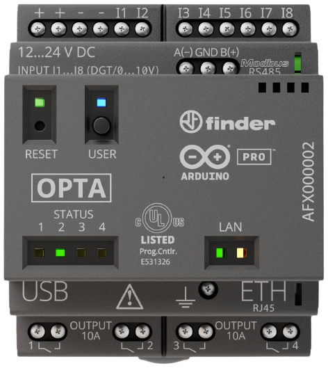
The Arduino Opta is a micro PLC with industrial IoT connectivity, made in partnership with the relay manufacturer Finder. Output Industries programs it with Busroot's data acquisition unit (DAU) firmware, which turns it into a simple, reliable way to send shop floor signals to Busroot.
The Opta is supplied pre-configured to connect to your network and send data to Busroot. To configure one yourself, see Arduino Opta configuration.
Wiring
- Power. Supply 12–24 V DC to the + and − pins at the top left of the unit. It uses no more than 2.2 W.
- Don't connect power to A(−) and B(+). These pins are for Modbus only, for example to connect an energy meter.
- Digital inputs. Use pins I1 to I6 on the top side for DC signals up to 24 V.
- Analogue inputs. Use pins I7 and I8 for 0–10 V analogue signals, such as line speed.
- Relays. The four relays on the bottom side are not used.
Each of the eight top pins can read a high or low signal from the machine or process you are monitoring. Before you power up:
- Check that power is connected only to the DC power pins.
- Check each input against its signal source, for example an andon light, an actuator or an optical sensor.
- Photograph the wiring of each machine for later checking.
When the Opta is installed, tell support the device ID printed on the front, the machine it is connected to, and which signal is on which pin.
Signals
Each pin captures one signal. You can use a single Opta for several machines or processes, because each pin is independent. The meaning of each pin is set in Busroot, not on the device.
Production complete
Pulse a pin each time a production cycle is completed. A pin can take up to 5 pulses a second: faster pulses may be missed. The Opta sends a pulse count for each pin every 5 seconds. Busroot receives it as production_complete.
Examples: the control signal of an exit gate actuator, or an optical sensor that detects parts leaving the process.
Productive time
Set a pin according to whether the process is actively producing or adding value. It doesn't matter whether the pin is high or low when productive: you set the meaning in Busroot. The Opta sends the state of each pin every 5 seconds. Busroot receives it as productive.
Examples: a CNC machine in its home position (not active), or a door sensor on a spray booth.
Line speed
Use pins I7 and I8 for an analogue signal of 0 to +10 V that follows the speed of the process. Busroot receives it as line_speed.
Examples: the control voltage of a conveyor motor drive, or the analogue output of a rotary encoder.
Connectivity
The Opta connects over Wi-Fi or, with an expansion module, over a cellular connection. It sends data to Busroot over MQTT. For the network requirements, hosts and ports, see Shop floor network.
Minimum Wi-Fi requirements
- 2.4 GHz Wi-Fi only.
- WPA2 with a pre-shared key (PSK).
- Signal strength of at least -80 dBm next to the equipment.
- Outbound internet access on the MQTT ports listed in Shop floor network.
LED codes
Watch the LED for at least 60 seconds before you decide what it shows.
| LED | Meaning |
|---|---|
| Flashing orange | Loading, or waiting for configuration |
| Red, 5 quick flashes | Wi-Fi problem |
| Red, 2 slow flashes | MQTT or internet problem |
| Green | Connected to Wi-Fi |
For a checklist of network causes, see Shop floor network troubleshooting.
Troubleshooting: reading device logs
Output Industries can supply a diagnostic device: an Android tablet with the Serial USB Terminal app installed. It works offline and doesn't need Wi-Fi or internet.
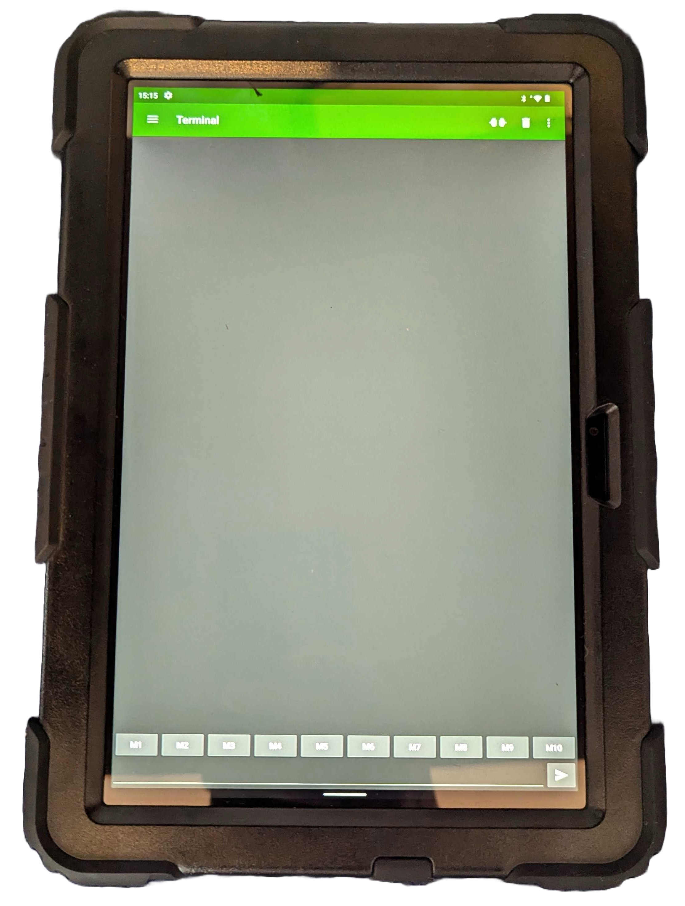
- Open the Serial USB Terminal app.
- Connect the diagnostic device to the Opta with a USB-C to USB-C cable.
-
If a message asks whether to connect the device to the app, confirm it.
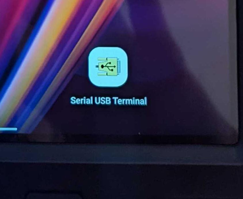
-
Press the connect icon at the top right.
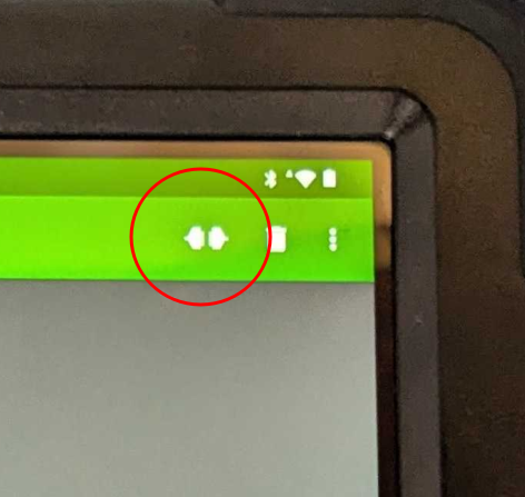
The Opta's logs now appear in the main terminal window.
Video walkthrough: https://www.loom.com/share/47f8ce0258c24f9d9a2d43dd44f8069c
Specifications
| Description | Value |
|---|---|
| Supply voltage | 12 to 24 V DC |
| Operating temperature range | -20 to 50 °C |
| Protection rating | IP20 |
| Power consumption (24 V) | 2.2 W maximum |
| Input impedance | 8.9 kΩ |
| Pollution degree | 2, conforming to IEC 61010 |
The Opta is IP20, so it must be mounted inside an enclosure, such as the machine's electrical cabinet. For hazardous areas, see ATEX enclosures.